INTRODUCTION
Chromatographic separation techniques are multistage separation methods in which the components of a sample are distributed between two phases, of which one is stationary and the other mobile. The stationary phase may be a solid or a liquid supported on a solid or a gel. The stationary phase may be packed in a column, spread as a layer, distributed as a film, or applied by other techniques. The mobile phase may be gaseous or liquid or supercritical fluid. The separation may be based on adsorption, mass distribution (partition), or ion exchange; or it may be based on differences among the physicochemical properties of the molecules, such as size, mass, and volume. This chapter contains general procedures, definitions, and calculations of common parameters and describes general requirements for system suitability. The types of chromatography useful in qualitative and quantitative analysis employed in USP procedures are column, gas, paper, thin-layer (including high-performance thin-layer chromatography), and pressurized liquid chromatography (commonly called high-pressure or high-performance liquid chromatography).
GENERAL PROCEDURES
This section describes the basic procedures used when a chromatographic method is described in a monograph. The following procedures are followed unless otherwise indicated in the individual monograph.
Paper Chromatography
Stationary Phase:
The stationary phase is a sheet of paper of suitable texture and thickness. Development may be ascending, in which the solvent is carried up the paper by capillary forces, or descending, in which the solvent flow is also assisted by gravitational force. The orientation of paper grain with respect to solvent flow is to be kept constant in a series of chromatograms. (The machine direction is usually designated by the manufacturer.)
Apparatus:
The essential equipment for paper chromatography consists of a vapor-tight chamber with inlets for addition of solvent and a rack of corrosion-resistant material about 5 cm shorter than the inside height of the chamber. The rack serves as a support for solvent troughs and for antisiphon rods that, in turn, hold up the chromatographic sheets. The bottom of the chamber is covered with the prescribed solvent system or mobile phase. Saturation of the chamber with solvent vapor is facilitated by lining the inside walls with paper wetted with the prescribed solvent system.
Spotting:
The substance or substances analyzed are dissolved in a suitable solvent. Convenient volumes, delivered from suitable micropipets, of the resulting solution, normally containing 1–20 µg of the compound, are placed in 6- to 10-mm spots not less than 3 cm apart.
Descending Paper Chromatography Procedure
- A spotted chromatographic sheet is suspended in the apparatus, using the antisiphon rod to hold the upper end of the sheet in the solvent trough. [Note—Ensure that the portion of the sheet hanging below the rods is freely suspended in the chamber without touching the rack, the chamber walls, or the fluid in the chamber. ]
- The chamber is sealed to allow equilibration (saturation) of the chamber and the paper with the solvent vapor. Any excess pressure is released as necessary.
- After equilibration of the chamber, the prepared mobile phase is introduced into the trough through the inlet.
- The inlet is closed, and the mobile solvent phase is allowed to travel the desired distance down the paper.
- The sheet is removed from the chamber.
- The location of the solvent front is quickly marked, and the sheet is dried.
- The chromatogram is observed and measured directly or after suitable development to reveal the location of the spots of the isolated drug or drugs.
Ascending Paper Chromatography Procedure
- The mobile phase is added to the bottom of the chamber.
- The chamber is sealed to allow equilibration (saturation) of the chamber and the paper with the solvent vapor. Any excess pressure is released as necessary.
- The lower edge of the stationary phase is dipped into the mobile phase to permit the mobile phase to rise on the chromatographic sheet by capillary action.
- When the solvent front has reached the desired height, the chamber is opened, the sheet is removed, the location of the solvent front is quickly marked, and the sheet is dried.
- The chromatogram is observed and measured directly or after suitable development to reveal the location of the spots of the isolated drug or drugs.
Thin-Layer Chromatography
Stationary Phase:
The stationary phase is a relatively thin, uniform layer of dry, finely powdered material applied to a glass, plastic, or metal sheet or plate (typically called the plate). The stationary phase of TLC plates has an average particle size of 10–15 µm, and that of high-performance TLC (HPTLC) plates has an average particle size of 5 µm. Commercial plates with a preadsorbent zone can be used if they are specified in a monograph. Sample applied to the preadsorbent region develops into sharp, narrow bands at the preadsorbent–sorbent interface. The separations achieved may be based on adsorption, partition, or a combination of both effects, depending on the particular type of stationary phase.
Apparatus:
A chromatographic chamber made of inert, transparent material and having the following specifications is used: a flat-bottom or twin trough, a tightly fitted lid, and a size suitable for the plates. The chamber is lined on at least one wall with filter paper. Sufficient mobile phase or developing solvent is added to the chamber that, after impregnation of the filter paper, a depth appropriate to the dimensions of the plate used is available. The chromatographic chamber is closed and allowed to equilibrate. [Note—Unless otherwise indicated, the chromatographic separations are performed in a saturated chamber. ]
Detection/Visualization:
An ultraviolet (UV) light source suitable for observations under short- (254 nm) and long- (365 nm) wavelength UV light and a variety of other spray reagents used to make spots visible are often used.
Spotting:
Solutions are spotted on the surface of the stationary phase (plate) at the prescribed volume in sufficiently small portions to obtain circular spots of 2–5 mm in diameter (1–2 mm on HPTLC plates) or bands of 10–20 mm × 1–2 mm (5–10 mm × 0.5–1 mm on HPTLC plates) at an appropriate distance from the lower edge of and sides of the plate. [Note—During development, the application position must be at least 5 mm (TLC) or 3 mm (HPTLC) above the level of the mobile phase. ] The solutions are applied on a line parallel to the lower edge of the plate with an interval of at least 10 mm (5 mm on HPTLC plates) between the centers of spots, or 4 mm (2 mm on HPTLC plates) between the edges of bands, then allowed to dry.
Procedure
- Place the plate in the chamber, ensuring that the spots or bands are above the surface of the mobile phase.
- Close the chamber.
- Allow the mobile phase to ascend the plate until the solvent front has traveled three-quarters of the length of the plate, or the distance prescribed in the monograph.
- Remove the plate, mark the solvent front with a pencil, and allow to dry.
- Visualize the chromatograms as prescribed.
- Determine the chromatographic retardation factor (RF) values for the principal spots or zones.
- Presumptive identification can be made by observation of spots or zones of identical RF value and about equal magnitude obtained, respectively, with an unknown and a standard chromatographed on the same plate. A visual comparison of the size or intensity of the spots or zones may serve for semiquantitative estimation. Quantitative measurements are possible by means of densitometry (absorbence or fluorescence measurements).
Column Chromatography
Solid Support:
Purified siliceous earth is used for normal-phase separation. Silanized chromatographic siliceous earth is used for reverse-phase partition chromatography.
Stationary Phase:
The solid support is modified by the addition of a stationary phase specified in the individual monograph. If a mixture of liquids is used as the stationary phase, mix the liquids before the introduction of the solid support.
Mobile Phase:
The mobile phase is specified in the individual monograph. If the stationary phase is an aqueous solution, equilibrate with water. If the stationary phase is a polar organic fluid, equilibrate with that fluid.
Apparatus:
Unless otherwise specified in the individual monograph, the chromatographic tube is about 22 mm in inside diameter and 200–300 mm long. Attached to it is a delivery tube, without stopcock, about 4 mm in inside diameter and about 50 mm long.
apparatus preparation:
Pack a pledget of fine glass wool in the base of the tube. Combine the specified volume of stationary phase and the specified amount of solid support to produce a homogeneous, fluffy mixture. Transfer this mixture to the chromatographic tube, and tamp, using gentle pressure, to obtain a uniform mass. If the specified amount of solid support is more than 3 g, transfer the mixture to the column in portions of approximately 2 g, and tamp each portion. If the assay or test requires a multisegment column with a different stationary phase specified for each segment, tamp after the addition of each segment, and add each succeeding segment directly to the previous one. Pack a pledget of fine glass wool above the completed column packing. [Note—The mobile phase should flow through a properly packed column as a moderate stream or, if reverse-phase chromatography is applied, as a slow trickle. ]
If a solution of the analyte is incorporated into the stationary phase, complete the quantitative transfer to the chromatographic tube by scrubbing the beaker used for the preparation of the test mixture with a mixture of about 1 g of Solid Support and several drops of the solvent used to prepare the sample solution before adding the final portion of glass wool.
Procedure
- Transfer the mobile phase to the column space above the column packing, and allow it to flow through the column under the influence of gravity.
- Rinse the tip of the chromatographic column with about 1 mL of mobile phase before each change in composition of mobile phase and after completion of the elution.
- If the analyte is introduced into the column as a solution in the mobile phase, allow it to pass completely into the column packing, then add mobile phase in several small portions, allowing each to drain completely, before adding the bulk of the mobile phase.
- Where the procedure indicates the use of multiple chromatographic columns mounted in series and the addition of mobile phase in divided portions is specified, allow each portion to drain completely through each column, and rinse the tip of each with mobile phase before the addition of each succeeding portion.
Gas Chromatography (GC)
Liquid Stationary Phase:
This type of phase is available in packed or capillary columns.
Packed Column GC:
The liquid stationary phase is deposited on a finely divided, inert solid support, such as diatomaceous earth, porous polymer, or graphitized carbon, which is packed into a column that is typically 2–4 mm in internal diameter and 1–3 m in length.
Capillary Column GC:
In capillary columns, which contain no packed solid support, the liquid stationary phase is deposited on the inner surface of the column and may be chemically bonded to it.
Solid Stationary Phase:
This type of phase is available only in packed columns. In these columns the solid phase is an active adsorbent, such as alumina, silica, or carbon, packed into a column. Polyaromatic porous resins, which are sometimes used in packed columns, are not coated with a liquid phase. [Note—Packed and capillary columns must be conditioned before use until the baseline and other characteristics are stable. The column or packing material supplier provides instructions for the recommended conditioning procedure. ]
Apparatus:
A gas chromatograph consists of a carrier gas source, injection port, column, detector, and recording device. The injection port, column, and detector are temperature controlled and may be varied as part of the analysis. The typical carrier gas is helium, nitrogen, or hydrogen, depending on the column and detector in use. The type of detector used depends on the nature of the compounds analyzed and is specified in the individual monograph. Detector output is recorded as a function of time, and the instrument response, measured as peak area or peak height, is a function of the amount present.
Temperature Program:
The length and quality of a GC separation can be controlled by altering the temperature of the chromatographic column. When a temperature program is necessary, the individual monograph indicates the conditions in table format. The table indicates the initial temperature, rate of temperature change (ramp), final temperature, and hold time at the final temperature.
Procedure
- Equilibrate the column, injector, and detector with flowing carrier gas until a constant signal is received.
- Inject a sample through the injector septum, or use an autosampler.
- Begin the temperature program.
- Record the chromatogram.
- Analyze as indicated in the monograph.
Liquid Chromatography (LC)
The term liquid chromatography, as used in the compendia, is synonymous with high-pressure liquid chromatography and high-performance liquid chromatography. LC is a separation technique based on a solid stationary phase and a liquid mobile phase.
Stationary Phase:
Separations are achieved by partition, adsorption, or ion-exchange processes, depending on the type of stationary phase used. The most commonly used stationary phases are modified silica or polymeric beads. The beads are modified by the addition of long-chain hydrocarbons. The specific type of packing needed to complete an analysis is indicated by the “L” designation in the individual monograph (see also the section Chromatographic Columns, below). The size of the beads is often described in the monograph as well. Changes in the packing type and size are covered in the System Suitability section of this chapter.
Chromatographic Column:
The term column includes stainless steel, lined stainless steel, and polymeric columns, packed with a stationary phase. The length and inner diameter of the column affects the separation, and therefore typical column dimensions are included in the individual monograph. Changes to column dimensions are discussed in the System Suitability section of this chapter. Compendial monographs do not include the name of appropriate columns; this omission avoids the appearance of endorsement of a vendor’s product and natural changes in the marketplace. See the section Chromatographic Columns for more information.
Mobile Phase:
The mobile phase is a solvent or a mixture of solvents, as defined in the individual monograph.
Apparatus:
A liquid chromatograph consists of a reservoir containing the mobile phase, a pump to force the mobile phase through the system at high pressure, an injector to introduce the sample into the mobile phase, a chromatographic column, a detector, and a data collection device.
Gradient Elution:
The technique of continuously changing the solvent composition during the chromatographic run is called gradient elution or solvent programming. The gradient elution profile is presented in the individual monograph as a gradient table, which lists the time and proportional composition of the mobile phase at the stated time.
Procedure
- Equilibrate the column and detector with mobile phase at the specified flow rate until a constant signal is received.
- Inject a sample through the injector, or use an autosampler.
- Begin the gradient program.
- Record the chromatogram.
- Analyze as directed in the monograph.
CHROMATOGRAPHIC COLUMNS
A complete list of packings (L), phases (G), and supports (S) used in USP–NF tests and assays is located in USP–NF and PF, Reagents, Indicators, and Solutions—Chromatographic Columns. This list is intended to be a convenient reference for the chromatographer in identifying the pertinent chromatographic column specified in the individual monograph.
DEFINITIONS AND INTERPRETATION OF CHROMATOGRAMS
Chromatogram:
A chromatogram is a graphical representation of the detector response, concentration of analyte in the effluent, or other quantity used as a measure of effluent concentration versus effluent volume or time. In planar chromatography, chromatogram may refer to the paper or layer with the separated zones.

Figure 1 represents a typical chromatographic separation of two substances, 1 and 2. tR1 and tR2 are the respective retention times; and h is the height, h/2 the half-height, and Wh/2 the width at half-height, for peak 1. W1 and W2 are the respective widths of peaks 1 and 2 at the baseline. Air peaks are a feature of gas chromatograms and correspond to the solvent front in LC. The retention time of these air peaks, or unretained components, is designated as tM.
+'&img=../../images/v35300/c621-f1-pf356.gif&casNumber=&usp=35&nf=30&chemicalStructureImage=false&ID='+parent.myID,600,500);)
Figure 1. Chromatographic separation of two substances.
Dwell Volume (D):
The dwell volume (also known as gradient delay volume) is the volume between the point at which the eluents meet and the top of the column.
Hold-Up Time (tM):
The hold-up time is the time required for elution of an unretained component (see Figure 1, shown as an air or unretained solvent peak, with the baseline scale in min).
Hold-Up Volume (VM):
The hold-up volume is the volume of mobile phase required for elution of an unretained component. It may be calculated from the hold-up time and the flow rate F, in mL/min:
VM = tM × F
In size exclusion chromatography, the symbol VO is used.
Number of Theoretical Plates (N)1:
N is a measure of column efficiency. For Gaussian peaks, it is calculated by:

N = 16(tR/W)2
where tR is the retention time of the substance, and W is the peak width at its base, obtained by extrapolating the relatively straight sides of the peak to the baseline. The value of N depends upon the substance being chromatographed as well as the operating conditions, such as the flow rate and temperature of the mobile phase or carrier gas, the quality of the packing, the uniformity of the packing within the column, and, for capillary columns, the thickness of the stationary phase film and the internal diameter and length of the column.
Where electronic integrators are used, it may be convenient to determine the number of theorical plates, by the equation:
+'&img=../../images/v35300/c621-eq1-pf356.gif&casNumber=&usp=35&nf=30&chemicalStructureImage=false&ID='+parent.myID,600,500);)
where Wh/2 is the peak width at half-height. However, in the event of dispute, only equations based on peak width at baseline are to be used.
Peak:
The peak is the portion of the chromatographic recording of the detector response when a single component is eluted from the column. If separation is incomplete, two or more components may be eluted as one unresolved peak.
Peak-to-Valley Ratio (p/v):
The p/v may be employed as a system suitability criterion in a test for related substances when baseline separation between two peaks is not achieved. Figure 2 represents a partial separation of two substances, where Hp is the height above the extrapolated baseline of the minor peak and Hv is the height above the extrapolated baseline at the lowest point of the curve separating the minor and major peaks:
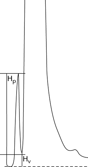
p/v = Hp/Hv
+'&img=../../images/v35300/c621-f2-pf356.gif&casNumber=&usp=35&nf=30&chemicalStructureImage=false&ID='+parent.myID,600,500);)
Figure 2.Peak-to-valley ratio determination.
Relative Retardation (Rret):
The relative retardation is the ratio of the distance traveled by the analyte to the distance simultaneously traveled by a reference compound (see Figure 3) and is used in planar chromatography.
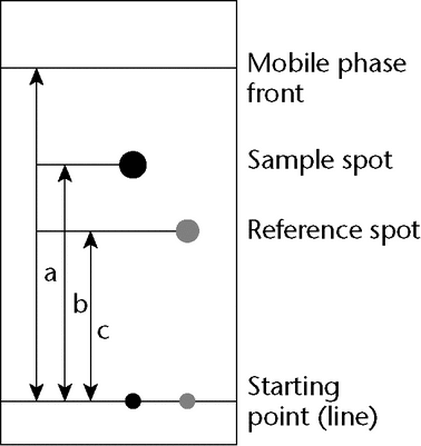
Rret = b / c
+'&img=../../images/v35300/c621-f3-pf356.gif&casNumber=&usp=35&nf=30&chemicalStructureImage=false&ID='+parent.myID,600,500);)
Figure 3.Typical planar chromatography.
Relative Retention (r)1:
Is the ratio of the adjusted retention time of a component relative to that of another used as a reference obtained under identical conditions:
r = tR2  tM/tR1 tM
where tR2 is the retention time measured from the point of injection of the compound of interest; tR1 is the retention time measured from the point of injection of the compound used as reference; and tM is the retention time of a nonretained marker defined in the procedure, all determined under identical experimental conditions on the same column.
Relative Retention Time (RRT):
Also known as unadjusted relative retention. Comparisons in USP are normally made in terms of unadjusted relative retention, unless otherwise indicated.
RRT = tR2/tR1
The symbol rG is also used to designate unadjusted relative retention values.
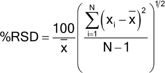
Relative Standard Deviation in Percentage
+'&img=../../images/v35300/c621-eq2-pf356.gif&casNumber=&usp=35&nf=30&chemicalStructureImage=false&ID='+parent.myID,600,500);)
Retardation Factor (RF):
The retardation factor is the ratio of the distance traveled by the center of the spot to the distance simultaneously traveled by the mobile phase and is used in planar chromatography. Using the symbols in Figure 3:
RF = b/a
Retention Factor (k)1:
The retention factor is also known as the capacity factor (k¢). Defined as:
 or
or

+'&img=../../images/v35300/g-986.gif&casNumber=&usp=35&nf=30&chemicalStructureImage=false&ID='+parent.myID,600,500);)
+'&img=../../images/v35300/c621-eq3-pf356.gif&casNumber=&usp=35&nf=30&chemicalStructureImage=false&ID='+parent.myID,600,500);)
The retention factor of a component may be determined from the chromatogram:
k = (tR tM)/tM
Retention Time (tR):
In liquid chromatography and gas chromatography, the retention time, tR, is defined as the time elapsed between the injection of the sample and the appearance of the maximum peak response of the eluted sample zone. tR may be used as a parameter for identification. Chromatographic retention times are characteristic of the compounds they represent but are not unique. Coincidence of retention times of a sample and a reference substance can be used as a partial criterion in construction of an identity profile but may not be sufficient on its own to establish identity. Absolute retention times of a given compound may vary from one chromatogram to the next.
Retention Volume (VR):
The retention volume is the volume of mobile phase required for elution of a component. It may be calculated from the retention time and the flow rate in mL/min:
VR = tR × F
Resolution (RS):
The resolution is the separation of two components in a mixture, calculated by:
RS = 2(tR2 tR1)/(W1 + W2)
where tR2 and tR1 are the retention times of the two components; and W2 and W1 are the corresponding widths at the bases of the peaks obtained by extrapolating the relatively straight sides of the peaks to the baseline.
Where electronic integrators are used, it may be convenient to determine the resolution, by the equation:
RS = 1.18(tR2 tR1)/(W1,h/2 + W2,h/2)
Separation Factor ( ):
The separation factor is the relative retention calculated for two adjacent peaks (by convention, the value of the separation factor is always >1):
= k2/k1
):
The separation factor is the relative retention calculated for two adjacent peaks (by convention, the value of the separation factor is always >1):
= k2/k1
Symmetry Factor (AS)2:
The symmetry factor (also known as the tailing factor) of a peak (see Figure 4) is calculated by:
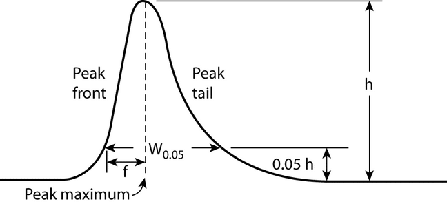
AS = W0.05/2f
where W0.05 is the width of the peak at 5% height and f is the distance from the peak maximum to the leading edge of the peak, the distance being measured at a point 5% of the peak height from the baseline.
+'&img=../../images/v35300/g-998.gif&casNumber=&usp=35&nf=30&chemicalStructureImage=false&ID='+parent.myID,600,500);)
Figure 4.Asymmetrical chromatographic peak.
Tailing Factor (T):
See Symmetry Factor.
SYSTEM SUITABILITY
System suitability tests are an integral part of gas and liquid chromatographic methods. These tests are used to verify that the chromatographic system is adequate for the intended analysis.
The tests are based on the concept that the equipment, electronics, analytical operations, and samples analyzed constitute an integral system that can be evaluated as such.
Factors that may affect chromatographic behavior include the following:
- Composition, ionic strength, temperature, and apparent pH of the mobile phase
- Flow rate, column dimensions, column temperature, and pressure
- Stationary phase characteristics, including type of chromatographic support (particle-based or monolithic), particle or macropore size, porosity, and specific surface area
- Reverse-phase and other surface modification of the stationary phases, the extent of chemical modification (as expressed by end-capping, carbon loading, etc.)
The resolution, RS, is a function of the number of theoretical plates, N (also referred to as efficiency), the separation factor, , and the capacity factor, k. [Note—All terms and symbols are defined in the preceding section Definitions and Interpretation of Chromatograms. ] For a given stationary phase and mobile phase, N may be specified to ensure that closely eluting compounds are resolved from each other, to establish the general resolving power of the system, and to ensure that internal standards are resolved from the drug. This is a less reliable means to ensure resolution than is direct measurement. Column efficiency is, in part, a reflection of peak sharpness, which is important for the detection of trace components.
Replicate injections of a standard preparation or other standard solutions are compared to ascertain whether requirements for precision are met. Unless otherwise specified in the individual monograph, data from five replicate injections of the analyte are used to calculate the relative standard deviation, %RSD, if the requirement is 2.0% or less; data from six replicate injections are used if the relative standard deviation requirement is more than 2.0%.
For the Assay in a drug substance monograph, where the value is 100% for the pure substance, and no maximum relative standard deviation is stated, the maximum permitted %RSD is calculated for a series of injections of the reference solution:
%RSD = KB n/t90%, n 1
where K is a constant (0.349), obtained from the expression K = (0.6/2) × (t 90%,5/6), in which 0.6/2 represents the required percentage relative standard deviation after six injections for B = 1.0; B is the upper limit given in the definition of the individual monograph minus 100%; n is the number of replicate injections of the reference solution (3  n 6); and t90%, n 1 is the Student’s t at the 90% probability level (double sided) with n 1 degrees of freedom.
Unless otherwise prescribed, the maximum permitted relative standard deviation does not exceed the appropriate value given in the table of repeatability requirements. This requirement does not apply to tests for related substances.
Relative Standard Deviation Requirements
| Number of Individual Injections | ||||
|---|---|---|---|---|
| 3 | 4 | 5 | 6 | |
| B (%) | Maximum Permitted RSD | |||
| 2.0 | 0.41 | 0.59 | 0.73 | 0.85 |
| 2.5 | 0.52 | 0.74 | 0.92 | 1.06 |
| 3.0 | 0.62 | 0.89 | 1.10 | 1.27 |
The symmetry factor, AS, a measure of peak symmetry, is unity for perfectly symmetrical peaks; and its value increases as tailing becomes more pronounced (see Figure 4). In some cases, values less than unity may be observed. As peak symmetry moves away from values of 1, integration, and hence precision, become less reliable.
The signal-to-noise ratio (S/N) is a useful system suitability parameter. The S/N is calculated as follows:
S/N = 2H/h
where H is the height of the peak measured from the peak apex to a baseline extrapolated over a distance  5 times the peak width at its half-height; and h is the difference between the largest and smallest noise values observed over a distance 5 times the width at the half-height of the peak and, if possible, situated equally around the peak of interest (see Figure 5).
+'&img=../../images/v35300/c621-f5-pf356.gif&casNumber=&usp=35&nf=30&chemicalStructureImage=false&ID='+parent.myID,600,500);)
Figure 5.Noise and chromatographic peak, components of the S/N ratio.
These system suitability tests are performed by collecting data from replicate injections of standard or other solutions as specified in the individual monograph.
The specification of definitive parameters in a monograph does not preclude the use of other suitable operating conditions. Adjustments are permitted only when
- Suitable standards (including Reference Standards) are available for all compounds used in the suitability test; and
- Those standards show that the adjustments improved the quality of the chromatography with respect to the system suitability requirements.
Adjustments to chromatographic systems performed in order to comply with system suitability requirements are not to be made in order to compensate for column failure or system malfunction.
If adjustments of operating conditions are necessary in order to meet system suitability requirements, each of the items in the following list is the maximum variation that can be considered, unless otherwise directed in the monograph; these changes may require additional validation data. To verify the suitability of the method under the new conditions, assess the relevant analytical performance characteristics potentially affected by the change. Multiple adjustments can have a cumulative effect on the performance of the system and are to be considered carefully before implementation. Adjustments to the composition of the mobile phase in gradient elution are not recommended. If adjustments are necessary, only column changes (same packing material) or dwell volume adjustments are recommended.
pH of Mobile Phase (HPLC):
The pH of the aqueous buffer used in the preparation of the mobile phase can be adjusted to within ±0.2 units of the value or range specified.
Concentration of Salts in Buffer (HPLC):
The concentration of the salts used in the preparation of the aqueous buffer employed in the mobile phase can be adjusted to within ±10% if the permitted pH variation (see above) is met.
Ratio of Components in Mobile Phase (HPLC):
The following adjustment limits apply to minor components of the mobile phase (specified at 50% or less). The amounts of these components can be adjusted by ±30% relative. However, the change in any component cannot exceed ±10% absolute (i.e., in relation to the total mobile phase). Adjustment can be made to one minor component in a ternary mixture. Examples of adjustments for binary and ternary mixtures are given below.
Binary Mixtures
specified ratio of 50:50:
30% of 50 is 15% absolute, but this exceeds the maximum permitted change of ±10% absolute in either component. Therefore, the mobile phase ratio may be adjusted only within the range of 40:60 to 60:40.
specified ratio of 2:98:
30% of 2 is 0.6% absolute. Therefore the maximum allowed adjustment is within the range of 1.4:98.6 to 2.6:97.4.
Ternary Mixtures
specified ratio of 60:35:5:
For the second component, 30% of 35 is 10.5% absolute, which exceeds the maximum permitted change of ±10% absolute in any component. Therefore the second component may be adjusted only within the range of 25% to 45% absolute. For the third component, 30% of 5 is 1.5% absolute. In all cases, a sufficient quantity of the first component is used to give a total of 100%. Therefore, mixture ranges of 50:45:5 to 70:25:5 or 58.5:35:6.5 to 61.5:35:3.5 would meet the requirement.
Wavelength of UV-Visible Detector (HPLC):
Deviations from the wavelengths specified in the procedure are not permitted. The procedure specified by the detector manufacturer, or another validated procedure, is used to verify that error in the detector wavelength is, at most, ±3 nm.
Stationary Phase
column length (gc, hplc):
Can be adjusted by as much as ±70%.
column Inner diameter (hplc):
Can be adjusted if the linear velocity is kept constant. See Flow Rate (HPLC) below.
column inner diameter (gc)—
Can be adjusted by as much as ±50% for GC.
film thickness (capillary cg)—
Can be adjusted by as much as 50% to 100%.
Particle Size (HPLC):
The particle size can be reduced by as much as 50%, but cannot be increased.
Particle Size (GC):
Changing from a larger to a smaller or from a smaller to a larger particle size GC mesh support is acceptable if the chromatography meets the requirements of system suitability and the same particle size range ratio is maintained. The particle size range ratio is defined as the diameter of the largest particle divided by the diameter of the smallest particle.
Flow Rate (GC):
The flow rate can be adjusted by as much as ±50%.
Flow Rate (HPLC):
When column dimensions have been modified, the flow rate can be adjusted using:

+'&img=../../images/v35300/c621-eq4-pf356.gif&casNumber=&usp=35&nf=30&chemicalStructureImage=false&ID='+parent.myID,600,500);)
in which F1 is the flow rate indicated in the monograph, in mL/min; F2 is the adjusted flow rate, in mL/min; l1 is the length of the column indicated in the monograph; l2 is the length of the column used; d1 is the column inner diameter indicated in the monograph; and d2 is the internal diameter of the column used. Additionally, the flow rate can be adjusted by ±50%.
Injection Volume (HPLC):
The injection volume can be reduced as far as is consistent with accepted precision and detection limits; no increase is permitted.
Injection Volume and Split Volume (GC):
The injection volume and split volume may be adjusted if detection and repeatability are satisfactory.
Column Temperature (HPLC):
The column temperature can be adjusted by as much as ±10 . Column thermostating is recommended to improve control and reproducibility of retention time.
Oven Temperature (GC):
The oven temperature can be adjusted by as much as ±10%.
Oven Temperature Program (GC):
Adjustment of temperatures is permitted as stated above. When the specified temperature must be maintained or when the temperature must be changed from one value to another, an adjustment of up to ±20% is permitted.
Unless otherwise directed in the monograph, system suitability parameters are determined from the analyte peak.
Measured values of Rr or RF or tR for the sample substance do not deviate from the values obtained for the reference compound and mixture by more than the statistically determined reliability estimates from replicate assays of the reference compound. Relative retention times may be provided in monographs for informational purposes only to aid in peak identification. There are no acceptance criteria applied to relative retention times.
Suitability testing is used to ascertain the effectiveness of the final operating system, which should be subjected to this testing. Make injections of the appropriate preparation(s) as required in order to demonstrate adequate system suitability (as described in the Chromatographic system section of the method in a monograph) throughout the run.
The preparation can be a standard preparation or a solution containing a known amount of analyte and any additional materials (e.g., excipients or impurities) useful in controlling the analytical system. Whenever there is a significant change in the chromatographic system (equipment, mobile phase component, or other components) or in a critical reagent, system suitability is to be reestablished. No sample analysis is acceptable unless the suitability of the system has been demonstrated.
QUANTITATION
During quantitation, disregard peaks caused by solvents and reagents or arising from the mobile phase or the sample matrix.
In the linear range, peak areas and peak heights are usually proportional to the quantity of compound eluting. The peak areas and peak heights are commonly measured by electronic integrators but may be determined by more classical approaches. Peak areas are generally used but may be less accurate if peak interference occurs. The components measured are separated from any interfering components. Peak tailing and fronting is minimized, and the measurement of peaks on tails of other peaks are avoided when possible.
Although comparison of impurity peaks with those in the chromatogram of a standard at a similar concentration is preferred, impurity tests may be based on the measurement of the peak response due to impurities and expressed as a percentage of the area of the drug peak. The standard may be the drug itself at a level corresponding to, for example, 0.5% impurity, assuming similar peak responses. When impurities must be determined with greater certainty, use a standard of the impurity itself or apply a correction factor based on the response of the impurity relative to that of the main component.
External Standard Method:
The concentration of the component(s) quantified is determined by comparing the response(s) obtained with the sample solution to the response(s) obtained with a standard solution.
Internal Standard Method:
Equal amounts of the internal standard are introduced into the sample solution and a standard solution. The internal standard is chosen so that it does not react with the test material, is stable, is resolved from the component(s) quantified (analytes), and does not contain impurities with the same retention time as that of the analytes. The concentrations of the analytes are determined by comparing the ratios of their peak areas or peak heights and the internal standard in the sample solution with the ratios of their peak areas or peak heights and the internal standard in the standard solution.
Normalization Procedure:
The percentage content of a component of the test material is calculated by determining the area of the corresponding peak as a percentage of the total area of all the peaks, excluding those due to solvents or reagents or arising from the mobile phase or the sample matrix and those at or below the limit at which they can be disregarded.
Calibration Procedure:
The relationship between the measured or evaluated signal y and the quantity (e.g., concentration, mass) of substance x is determined, and the calibration function is calculated. The analytical results are calculated from the measured signal or evaluated signal of the analyte and its position on the calibration curve.
In tests for impurities for both the External Standard Method, when a dilution of the sample solution is used for comparison, and the Normalization Procedure, any correction factors indicated in the monograph are applied (e.g., when the response factor is outside the range 0.8–1.2).
When the impurity test prescribes the total of impurities or there is a quantitative determination of an impurity, choice of an appropriate threshold setting and appropriate conditions for the integration of the peak areas is important. In such tests the limit at or below which a peak is disregarded is generally 0.05%. Thus, the threshold setting of the data collection system corresponds to at least half of this limit. Integrate the peak area of any impurity that is not completely separated from the principal peak, preferably by valley-to-valley extrapolation (tangential skim).
1
The parameters k, N, r, and rG were developed for isothermal GC separations and isocratic HPLC separations. Because these terms are thermodynamic parameters, they are valid only for separations made at constant temperature, mobile phase composition, and flow rate. However, for separations made with a temperature program or solvent gradient, these parameters may be used simply as comparative means to ensure that adequate chromatographic conditions exist to perform the methods as intended in the monographs.
2
It is also a common practice to measure the Asymmetry Factor as the ratio of the distance between the vertical line connecting the peak apex with the interpolated baseline and the peak front, and the distance between that line and the peak back measured at 10% of the peak height (see Figure 4), would be (W0.10 f0.10)/f0.10. However, for the purposes of USP, only the formula (As) as presented here is valid.
Auxiliary Information—
Please check for your question in the FAQs before contacting USP.
| Topic/Question | Contact | Expert Committee |
|---|---|---|
| General Chapter | Horacio N. Pappa, Ph.D.
Principal Scientific Liaison 1-301-816-8319 |
(GCCA2010) General Chapters - Chemical Analysis |
USP35–NF30 Page 258
Pharmacopeial Forum: Volume No. 37(3)