This general information chapter Apparent Intrinsic Dissolution—Dissolution Testing Procedures for Rotating Disk and Stationary Disk  1087
1087 discusses the determination of dissolution rates from nondisintegrating compacts exposing a fixed surface area to a given solvent medium. Compact, as used here, is a nondisintegrating mass resulting from compression of the material under test using appropriate pressure conditions. A single surface having specified physical dimensions is presented for dissolution. Determination of the rate of dissolution can be important during the course of the development of new chemical entities because it sometimes permits prediction of potential bioavailability problems and may also be useful to characterize compendial articles such as excipients or drug substances. Intrinsic dissolution studies are characterization studies and are not referenced in individual monographs. Information provided in this general information chapter is intended to be adapted via a specific protocol appropriate to a specified material.
Dissolution rate generally is expressed as the mass of solute appearing in the dissolution medium per unit time (e.g., mass sec–1), but dissolution flux is expressed as the rate per unit area (e.g., mass cm–2 sec–1). Reporting dissolution flux is preferred because it is normalized for surface area, and for a pure drug substance is commonly called intrinsic dissolution rate. Dissolution rate is influenced by intrinsic solid-state properties such as crystalline state, including polymorphs and solvates, as well as degree of noncrystallinity. Numerous procedures are available for modifying the physicochemical properties of chemical entities so that their solubility and dissolution properties are enhanced. Among these are coprecipitates and the use of racemates and enantiomeric mixtures. The effect of impurities associated with a material can also significantly alter its dissolution properties. Dissolution properties are also influenced by extrinsic factors such as surface area, hydrodynamics, and dissolution medium properties, including solvent (typically water), presence of surfactants, temperature, fluid viscosity, pH, buffer type, and buffer strength.
Rotating disk and stationary disk dissolution procedures are sufficiently versatile to allow the study of characteristics of compounds of pharmaceutical interest under a variety of test conditions. Characteristics common to both apparatuses include the following:
- They are adaptable to use with standard dissolution testing stations, and both use a tablet die to hold the nondisintegrating compact during the dissolution test.
- They rely on compression of the test compound into a compact that does not flake or fall free during the dissolution test.
- A single surface of known geometry and physical dimension is presented for dissolution.
- The die is located at a fixed position in the vessel, which decreases the variation of hydrodynamic conditions.
A difference between the two procedures is the source of fluid flow over the dissolving surface. In the case of the rotating disk procedure, fluid flow is generated by the rotation of the die in a quiescent fluid, but fluid flow is generated by a paddle or other stirring device for the stationary disk procedure.
EXPERIMENTAL PROCEDURE
The procedure for carrying out dissolution studies with the two types of apparatus consists of preparing a nondisintegrating compact of material using a suitable compaction device, placing the compact and surrounding die assembly in a suitable dissolution medium, subjecting the compact to the desired hydrodynamics near the compact surface, and measuring the amount of dissolved solute as a function of time.
Compacts are typically prepared using an apparatus that consists of a die, an upper punch, and a lower surface plate fabricated out of hardened steel or other material that allows the compression of material into a nondisintegrating compact. An alternative compaction apparatus consists of a die and two punches. Other configurations that achieve a nondisintegrating compact of constant surface area also may be used. The nondisintegrating compact typically has a diameter of 0.2 cm to 1.5 cm.
Compact Preparation
Attach the smooth lower surface plate to the underside of the die, or alternatively, insert the lower punch using an appropriate clamping system. Accurately weigh a quantity of material necessary to achieve an acceptable compact and transfer to the die cavity. Place the upper punch into the die cavity, and compress the powder on a hydraulic press at a compression pressure required to form a nondisintegrating compact that will remain in the die assembly for the length of the test. Compression for 1 minute at 15 MPa usually is sufficient for many organic crystalline compounds, but alternative compression conditions that avoid the formation of capillaries should be evaluated. For a given substance, the compact preparation, once optimized is standardized to facilitate comparison of different samples of the substance.
Changes in crystalline form may occur during compression; therefore, confirmation of solid state form should be performed by powder X-ray diffraction or other similar technique. Remove the surface plate or lower punch. Remove loose powder from the surface of the compact and die by blowing compressed air or nitrogen over the surface.
Dissolution Medium
The choice of dissolution medium is an important consideration. Whenever possible, testing should be performed under sink conditions to avoid artificially retarding the dissolution rate due to approach of solute saturation of the medium. Dissolution measurements are typically made in aqueous media. To approximate in vivo conditions, measurements may be run in the physiological pH range at 37 . The procedure when possible is carried out under the same conditions that are used to determine the intrinsic solubility of the solid state form being tested. Dissolution media should be deaerated immediately prior to use to avoid air bubbles forming on the compact or die surface.1
The medium temperature and pH must be controlled, especially when dealing with ionizable compounds and salts. In the latter cases, the dissolution rate may depend strongly on the pH, buffer species, and buffer concentration. A simplifying assumption in constant surface area dissolution testing is that the pH at the surface of the dissolving compact is the same as the pH of the bulk dissolution medium. For nonionizable compounds, this is relatively simple because no significant pH dependence on dissolution rate is expected. For acids and bases, the solute can alter the pH at and near the surface of the compact as it dissolves. Under these conditions, the pH at the surface of the compact may be quite different from the bulk pH due to the self-buffering capacity of the solute. To assess intrinsic solubility, experimental conditions should be chosen to eliminate the effect of solute buffering, alteration of solution pH, and precipitation of other solid state forms at the surface of the compact. For weak acids, the pH of the dissolution medium should be one to two pH units below the pKa of the dissolving species. For weak bases, the pH of the dissolution medium should be one to two pH units above the pKa of the dissolving species.
Apparatus
Rotating Disk—
A typical apparatus (Figure 1) consists of a punch and die fabricated out of hardened steel. The base of the die has three threaded holes for the attachment of a surface plate made of polished steel, providing a mirror-smooth base for the compacted pellet. The die has a cavity into which is placed a measured amount of the material whose intrinsic dissolution rate is to be determined. The punch is then inserted in the die cavity and the test material is compressed with a hydraulic press. [note—A hole through the head of the punch allows insertion of a metal rod to facilitate removal from the die after the test.] A compacted pellet of the material is formed in the cavity with a single face of defined area exposed on the bottom of the die.
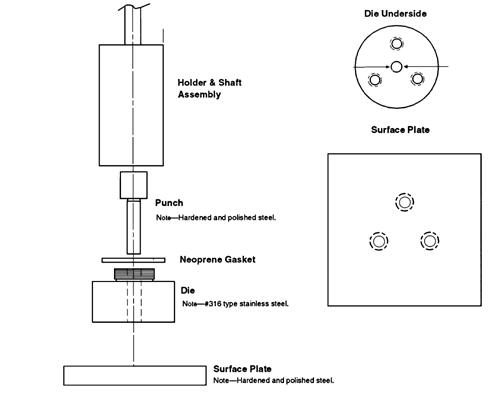
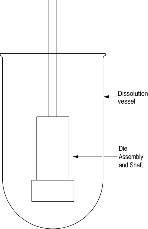
Figure 1
The die assembly is then attached to a shaft constructed of an appropriate material (typically steel). The shaft holding the die assembly is positioned so that when the die assembly is lowered into the dissolution medium (Figure 2) the exposed surface of the compact will be not less than 1.0 cm from the bottom of the vessel and nominally in a horizontal position. The die assembly should be aligned to minimize wobble, and air bubbles should not be allowed to form on the compact or die surface.
Figure 2
A rotating disk speed of 300 rpm is recommended. Typical rotation speeds may range from 60 rpm to 500 rpm. The dissolution rate depends on the rotation speed used. This parameter should be selected in order to admit at least five sample points during the test, but excessive stirring speeds may create shear patterns on the surface of the dissolving material that could cause aberrant results (i.e., nonlinearity). Typically, the concentration of the test specimen is measured as a function of time, and the amount dissolved is then calculated. The sampling interval will be determined by the speed of the dissolution process. If samples are removed from the dissolution medium, the cumulative amount dissolved at each time point should be corrected for losses due to sampling.
Stationary Disk—
The apparatus (Figure 3) consists of a steel punch, die, and a base plate. The die base has three holes for the attachment of the base plate. The three fixed screws on the base plate are inserted through the three holes on the die and then fastened with three washers and nuts. The test material is placed into the die cavity. The punch is then inserted into the cavity and compressed, with the aid of a bench top press. The base plate is then disconnected from the die to expose a smooth compact pellet surface. A gasket is placed around the threaded shoulder of the die and a polypropylene cap is then screwed onto the threaded shoulder of the die.
The die assembly is then positioned at the bottom of a specially designed dissolution vessel with a flat bottom (Figure 4). The stirring unit (e.g., paddle) is positioned at an appropriate distance (typically 2.54 cm) from the compact surface. The die assembly and stirring unit should be aligned to ensure consistent hydrodynamics, and air bubbles should not be present on the compact surface during testing. Alternative configurations may be utilized if adequate characterization and control of the hydrodynamics can be established.
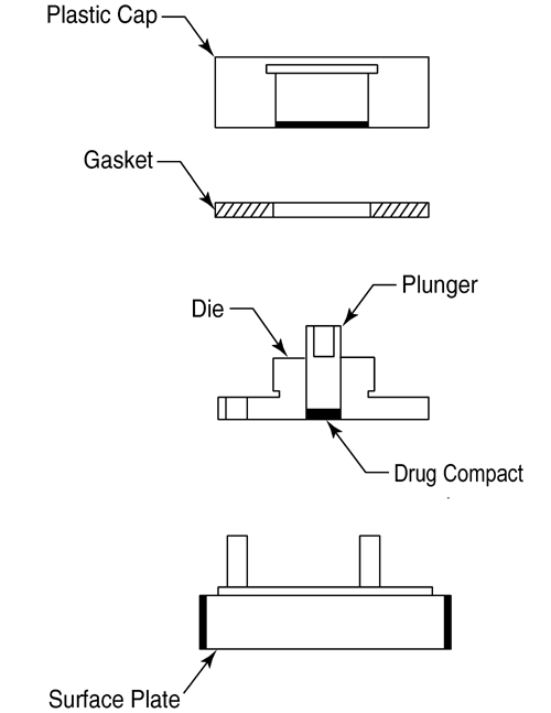
Figure 3
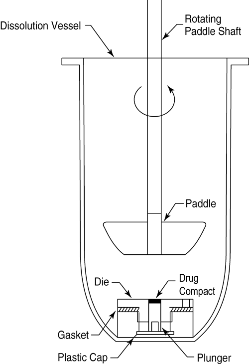
Figure 4
The dissolution rate depends on the rotation speed and precise hydrodynamics that exist. Typically, the concentration of the test specimen is measured as a function of time, and the amount dissolved is then calculated. The sampling interval will be determined by the speed of the dissolution process (see Rotating Disk). If samples are removed from the dissolution medium, the cumulative amount dissolved at each time point should be corrected for losses due to sampling.
DATA ANALYSIS AND INTERPRETATION
The dissolution rate is determined by plotting the cumulative amount of solute dissolved against time. Linear regression analysis is performed on data points in the initial linear region of the dissolution curve. The slope corresponds to the dissolution rate (mass sec–1). (More precise estimates of slope can be obtained using a generalized linear model that takes into account correlations among the measurements of the cumulative amounts dissolved at the various sampling times.)
The amount versus time profiles may show curvature. When this occurs, only the initial linear portion of the profile is used to determine the dissolution rate. Upward curvature (positive second derivative) of the concentration versus time data is typically indicative of a systematic experimental problem. Possible problems include physical degradation of the compact by cracking, delaminating, or disintegration. Downward (negative second derivative) curvature of the dissolution profile is often indicative of a transformation of the solid form of the compact at the surface or when saturation of the dissolution medium is inadvertently being approached. This often occurs when a less thermodynamically stable crystalline form converts to a more stable form. Examples include conversion from an amorphous form to a crystalline form or from an anhydrous form to a hydrate form, or the formation of a salt or a salt converting to the corresponding free acid or free base. If such curvature is observed, the crystalline form of the compact may be assessed by removing it from the medium and examining it by powder X-ray diffraction or another similar technique to determine if the exposed surface area is changing.
The constant surface area dissolution rate is reported in units of mass sec–1, and the dissolution flux is reported in units of mass cm–2 sec–1. The dissolution flux is calculated by dividing the dissolution rate by the surface area of the compact. Test conditions, typically a description of the apparatus, rotation speed, temperature, buffer species and strength, pH, and ionic strength should also be reported with the analyses.
1
One method of deaeration is as follows: Heat the medium, while stirring gently, to about 41, immediately filter under vacuum using a filter having a porosity of 0.45 µm or less, with vigorous stirring, and continue stirring under vacuum for about 5 minutes. Other deaeration techniques for removal of dissolved gases may be used.
Auxiliary Information— Please check for your question in the FAQs before contacting USP.
| Topic/Question | Contact | Expert Committee |
| General Chapter | William E. Brown
Senior Scientist 1-301-816-8380 |
(BPC05) Biopharmaceutics05 |
USP32–NF27 Page 549
Pharmacopeial Forum: Volume No. 33(2) Page 269