- British Pharmacopoeia Volume IV
- Appendices
Appendix V H. Viscosity |


The dynamic viscosity or viscosity coefficient η is the tangential force per unit surface, known as shearing stress τ and expressed in pascals, necessary to move, parallel to the sliding plane, a layer of liquid of 1 square metre at a rate (v) of 1 metre per second relative to a parallel layer at a distance (x) of 1 metre.
The ratio dv/dx is a speed gradient giving the rate of shear D expressed in reciprocal seconds (s-1), so that η = τ/D.
The unit of dynamic viscosity is the pascal second (Pa·s). The most commonly used submultiple is the millipascal second (mPa·s).
The kinematic viscosity v, expressed in square metres per second, is obtained by dividing the dynamic viscosity η by the density ρ expressed in kilograms per cubic metre, of the liquid measured at the same temperature, i.e. v = η/ρ. The kinematic viscosity is usually expressed in square millimetres per second.
A capillary viscometer may be used for determining the viscosity of Newtonian liquids and a rotating viscometer for determining the viscosity of Newtonian and non-Newtonian liquids. Other viscometers may be used provided that the accuracy and precision is not less than that obtained with the viscometers described below.
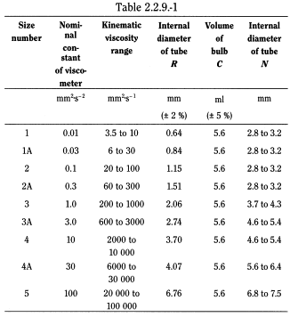
The apparatus consists of a glass U-tube viscometer (Fig.5H–1) made of clear borosilicate glass and constructed in accordance with the dimensions shown in the figure and in Table 5H–1. The monograph states the size of viscometer to be used.
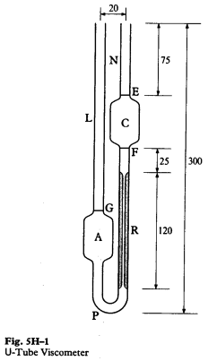

Fill the viscometer with the liquid being examined through tube L to slightly above the mark G, using a long pipette to minimise wetting the tube above the mark. Place the tube vertically in a water bath and when it has attained the specified temperature, adjust the volume of the liquid so that the bottom of the meniscus settles at the mark G. Adjust the liquid to a point about 5 mm above the mark E. After releasing pressure or suction, measure the time taken for the bottom of the meniscus to fall from the top edge of mark E to the top edge of mark F.
Calculate, as required, either the kinematic viscosity (ν) in square millimetres per second (mm2 s–1) from the expression:
ν = Kt,
or the dynamic viscosity (η) in millipascal seconds (mPa s) from the expression:
η = Kρt,
where |
t |
= |
time in seconds for the meniscus to fall from E to F, |
ρ |
= |
mass/volume (g cm–3) obtained by multiplying the relative density, Appendix V G, of the fluid being examined by 0.9982. |
The constant (K) of the instrument is determined using the appropriate European Pharmacopoeia reference liquid for viscometers.
The determination of viscosity using a suitable capillary viscometer is carried out at a temperature of 20 ± 0.1 °C, unless otherwise prescribed. The time required for the level of the liquid to drop from one mark to the other is measured with a stop-watch to the nearest one-fifth of a second. The result is valid only if two consecutive readings do not differ by more than 1 per cent. The average of not fewer than three readings gives the flow time of the liquid to be examined.
Calculate the dynamic viscosity η (2.2.8) in millipascal seconds using the formula:

k |
= |
constant of the viscometer, expressed in square millimetres per second squared, |
ρ |
= |
density of the liquid to be examined expressed in milligrams per cubic millimetre, obtained by multiplying its relative density ( |
t |
= |
flow time, in seconds, of the liquid to be examined. |
 ) by 0.9982,
The constant k is determined using a suitable viscometer calibration liquid.
To calculate the kinematic viscosity (mm2·s-1), use the following formula: v = kt.
The determination may be carried out with an apparatus (Figure 2.2.9.-1) having the specifications described in Table 2.2.9.-11:
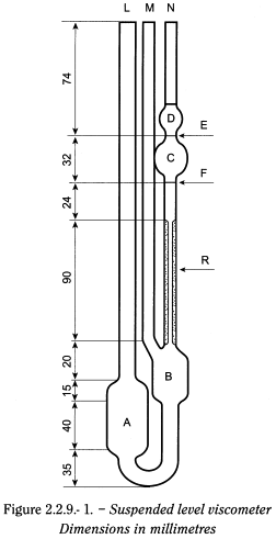
The minimum flow time should be 350 s for size no. 1 and 200 s for all other sizes.
Method Fill the viscometer through tube (L) with a sufficient quantity of the liquid to be examined, previously brought to 20 °C unless otherwise prescribed, to fill bulb (A) but ensuring that the level of liquid in bulb (B) is below the exit to ventilation tube (M). Immerse the viscometer in the bath of water at 20 ± 0.1 °C, unless otherwise prescribed, maintain it in the upright position and allow to stand for not less than 30 min to allow the temperature to reach equilibrium. Close tube (M) and raise the level of the liquid in tube (N) up to a level about 8 mm above mark (E). Keep the liquid at this level by closing tube (N) and opening tube (M). Open tube (N) and measure, with a stop-watch to the nearest one-fifth of a second, the time required for the level of the liquid to drop from mark (E) to (F).
The principle of the method is to measure the force acting on a rotor (torque) when it rotates at a constant angular velocity (rotational speed) in a liquid. Rotating viscometers are used for measuring the viscosity of Newtonian (shear-independent viscosity) or non-Newtonian liquids (shear dependent viscosity or apparent viscosity). Rotating viscometers can be divided in 2 groups, namely absolute and relative viscometers. In absolute viscometers the flow in the measuring geometry is well defined. The measurements result in absolute viscosity values, which can be compared with any other absolute values. In relative viscometers the flow in the measuring geometry is not defined. The measurements result in relative viscosity values, which cannot be compared with absolute values or other relative values if not determined by the same relative viscometer method.
Different measuring systems are available for given viscosity ranges as well as several rotational speeds.
Apparatus The following types of instruments are most common.
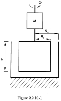
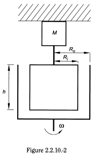
In the concentric cylinder viscometer (coaxial double cylinder viscometer or simply coaxial cylinder viscometer), the viscosity is determined by placing the liquid in the gap between the inner cylinder and the outer cylinder. Viscosity measurement can be performed by rotating the inner cylinder (Searle type viscometer) or the outer cylinder (Couette type viscometer), as shown in Figures 2.2.10.-1 and 2.2.10.-2, respectively. For laminar flow, the viscosity (or apparent viscosity) η expressed in pascal-seconds is given by the following formula:
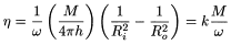
M |
= |
torque in newton-metres acting on the cylinder surface, |
ω |
= |
angular velocity in radians per second, |
h |
= |
height of immersion in metres of the inner cylinder in the liquid medium, |
Ri |
= |
radius in metres of the inner cylinder, |
Ro |
= |
radius in metres of the outer cylinder, |
k |
= |
constant of the apparatus, expressed in radians per cubic metre. |
For non-Newtonian liquids it is indispensable to specify the shear stress (τ) or the shear rate (γ) at which the viscosity is measured. Under narrow gap conditions (conditions satisfied in absolute viscometers), there is a proportional relationship between M and τ and also between ω and γ:
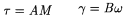
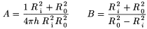
where A and B are constants for the instrument and are calculated from the following expressions:
- — for concentric surface:
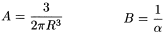
- — for cone-plates:
M |
= |
torque in Newton-metres acting on the cone or cylinder surface, |
ω |
= |
angular velocity in radians per second, |
Ri |
= |
radius in metres of the inner cylinder, |
R0 |
= |
radius in metres of the outer cylinder, |
R |
= |
radius in metres of the cone, |
h |
= |
height of immersion in metres of the inner cylinder in the liquid medium, |
α |
= |
angle in radians between the flat disk and the cone, |
τ |
= |
shear stress in pascals (Pa), |
γ |
= |
shear rate in reciprocal seconds (s-1) |
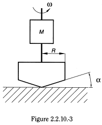
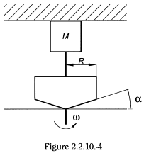
In the cone-plate viscometer, the liquid is introduced into the gap between a flat disc and a cone forming a define angle. Viscosity measurement can be performed by rotating the cone or the flat disc, as shown in Figures 2.2.10.-3 and 2.2.10.-4, respectively. For laminar flow, the viscosity (or apparent viscosity) η expressed in pascal-seconds is given by the following formula:
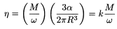
M |
= |
torque in Newton-metres acting on the flat disc or cone surface, |
ω |
= |
angular velocity in radians per second, |
α |
= |
angle in radians between the flat disc and the cone, |
R |
= |
radius in metres of the cone, |
k |
= |
constant of the apparatus, expressed in radians per cubic metre. |
Constants A, B of the apparatus (see under concentric cylinder viscometers).
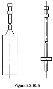
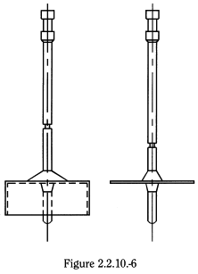
In the spindle viscometer, the viscosity is determined by rotating a spindle (for example, cylinder- or disc-shaped, as shown in Figures 2.2.10.-5 and 2.2.10.-6, respectively) immersed in the liquid. Relative values of viscosity (or apparent viscosity) can be directly calculated using conversion factors from the scale reading at a given rotational speed.
In a general way, the constant k of the apparatus may be determined at various speeds of rotation using a certified viscometer calibration liquid. The viscosity η then corresponds to the formula:

Method Measure the viscosity (or apparent viscosity) according to the instructions for the operation of the rotating viscometer. The temperature for measuring the viscosity is indicated in the monograph. For non-Newtonian systems, the monograph indicates the type of viscometer to be used and if absolute viscometers are used the angular velocity or the shear rate at which the measurement is made. If it is impossible to obtain the indicated shear rate exactly, use a shear rate slightly higher and a shear rate slightly lower and interpolate.
With relative viscometers the shear rate is not the same throughout the sample and therefore it cannot be defined. Under these conditions, the viscosity of non-Newtonian liquids determined from the previous formula has a relative character, which depends on the type of spindle and the angular velocity as well as the dimensions of the sample container (Ø = minimum 80 mm) and the depth of immersion of the spindle. The values obtained are comparable only if the method is carried out under experimental conditions that are rigorously the same.
The determination of dynamic viscosity of Newtonian liquids using a suitable falling ball viscometer is performed at 20 ± 0.1 °C, unless otherwise prescribed in the monograph. The time required for a test ball to fall in the liquid to be examined from one ring mark to the other is determined. If no stricter limit is defined for the equipment used the result is valid only if 2 consecutive measures do not differ by more than 1.5 per cent.
Apparatus The falling ball viscometer consists of: a glass tube enclosed in a mantle, which allow precise control of temperature; six balls made of glass, nickel-iron or steel with different densities and diameters. The tube is fixed in such a way that the axis is inclined by 10 ± 1° with regard to the vertical. The tube has 2 ring marks which define the distance the ball has to roll. Commercially available apparatus is supplied with tables giving the constants, the density of the balls and the suitability of the different balls for the expected range of viscosity.
Method Fill the clean, dry tube of the viscometer, previously brought to 20 ± 0.1 °C, with the liquid to be examined, avoiding bubbles. Add the ball suitable for the range of viscosity of the liquid so as to obtain a falling time not less than 30 s. Close the tube and maintain the solution at 20 ± 0.1 °C for at least 15 min. Let the ball run through the liquid between the 2 ring marks once without measurement. Let it run again and measure with a stop-watch, to the nearest one-fifth of a second, the time required for the ball to roll from the upper to the lower ring mark. Repeat the test run at least 3 times.
Calculate the dynamic viscosity η in millipascal seconds using the formula:
k |
= |
constant, expressed in millimeter squared per second squared, |
ρ1 |
= |
density of the ball used, expressed in grams per cubic centimetre, |
ρ2 |
= |
density of the liquid to be examined, expressed in grams per cubic centimetre, obtained by multiplying its relative density |
t |
= |
falling time of the ball, in seconds. |
The apparatus and methods described in Methods I and II are in agreement in all essentials with International Standards ISO 3104-1994 and 3105-1994 (Methods for the determination of the viscosity of liquids).
1The European Pharmacopoeia describes the system proposed by the International Organisation for Standardisation (2Commercially available apparatus is supplied with tables giving the constants of the apparatus in relation to the surface area of the cylinders used and their speed of rotation.